Metallographic
Atlas - example pages from the printed version
1a. Etching methods to make the microstructure visible.
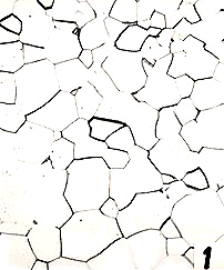
Micrograph 1. An etching reagent may attack different crystals
with different rates depending upon the difference in crystallographic orientation.
There will thus be a sharp step at the crystal boundaries. In the microscope one
will see a black line. (This picture is a reproduction of a previously printed
picture. This has given rise to a so-called Moiré pattern, a regular pattern of
brighter and darker areas covering the whole picture. It is sometimes much finer
than shown here. See picture 3, for example.)
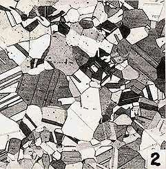
Micrograph 2.
An etching reagent may colour different crystals differently due to their different
crystallographic orientation. In a black and white micrograph this may give rise to
different shades of grey. Picture 2 is taken on an fcc Cu-Zn alloy and shows that
the grains have annealing twins.
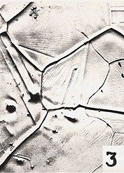
Micrograph 3. An etching reagent may attack crystal boundaries and form grooves. They will show up as black lines in the microscope. Oblique illumination can reveal that the black line is not due to a step (as in picture 1). Actually, the grooves in picture 3 were formed by thermal etching (annealing at high temperature in vacuum) and are deeper and wider than one normally gets with chemical etching.
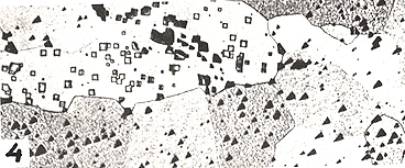
Micrograph 4. An etching reagent may attack the surface of a crystal in such a way that facets of low indices are formed. This may result in etch pits as shown here. In this case the facets are {100}. The orientation of the crystal is thus revealed. This micrograph was taken on a coarse-grained specimen of a bcc Fe-Si alloy.
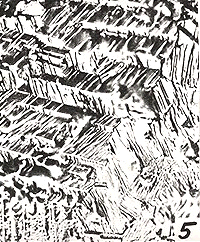
Micrograph 5. This is another example of facetting etching where the whole surface has been attacked. The material is pure Fe.
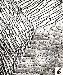
Micrograph 6. This is similar to picture 5 but the etching conditions were slightly different.
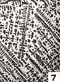
Micrograph 7. The attack of the etching reagent may depend on the chemical composition and may not reveal the crystal boundaries if there is no sharp change in composition there. This micrograph shows the inhomogeneous distribution of alloying elements in a Cu alloy, caused by segregation during dendritic solidification.
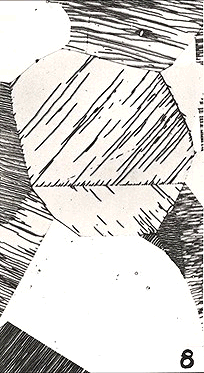
Micrograph 8. The etching reagent may give solid reaction products which deposit on the surface, usually as a dark or coloured film. The film sometimes cracks when the specimen is dried and a pattern of lines may form which has some relation to the orientation of the crystal. This micrograph is taken on an fcc Cu-Zn alloy and the horizontal line reveals a coherent twin boundary.
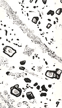
Micrograph 9. The etching reagent may attack different phases in different ways. Here the thin white phase has not been attacked at all. The grey matrix has been attacked and thus there is now a step at the interfaces between white and grey crystals. In addition, the grey phase is grey because it contained a hugh number of very fine particles of a different phase which was not dissolved and stayed as dirt on the surface. The black phase was attacked in such a way that a solid reaction product deposited on the surface. White and black phases are two different alloyed carbides and the grey phase is martensite which has been slightly annealed.
Last change: 19 of Dec 1996
Lars Fredrik Larsson
larsf@matsc.kth.se 


